New Horizons

Jessie Johnson

Spring, 2020

Project Outline

The goal for this project was to create an easily recognizable sign to signify my work, personality, and interests. The sign needed to be created with vacuum formed plastic, which meant that there was an accompanying mold to be made as well. Accounting for the many variables involved in the processes of vacuum forming and making the mold were the greatest challenges in this project. The design needed to be able to adapt to these variables which required extensive problem solving and planning. Documentation of the designing process is detailed below, describing the steps taken to bring the idea to reality.

Concept Development

Visualization & Planning

Building Process

Final

Concept Development

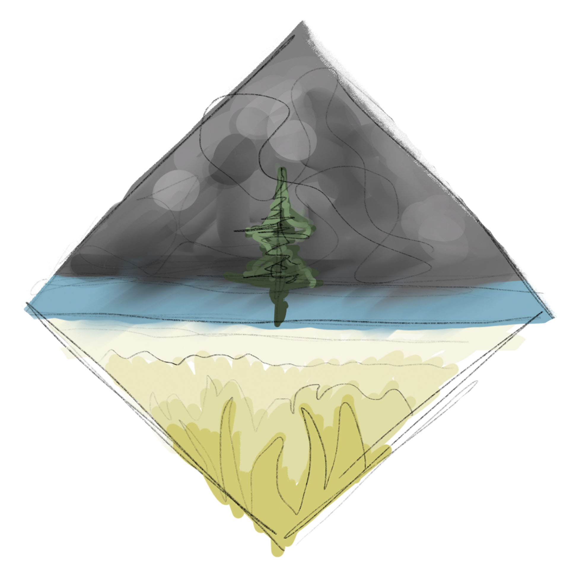
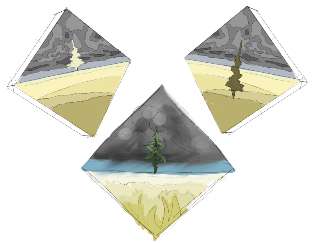
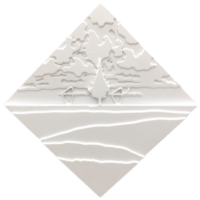
Since my family is from the Midwest and I spent the early years of my life there, it holds a special place in my heart. What defined the Midwest for me was the sky, land, and powerful storms. My goal was to highlight these features in my concept.

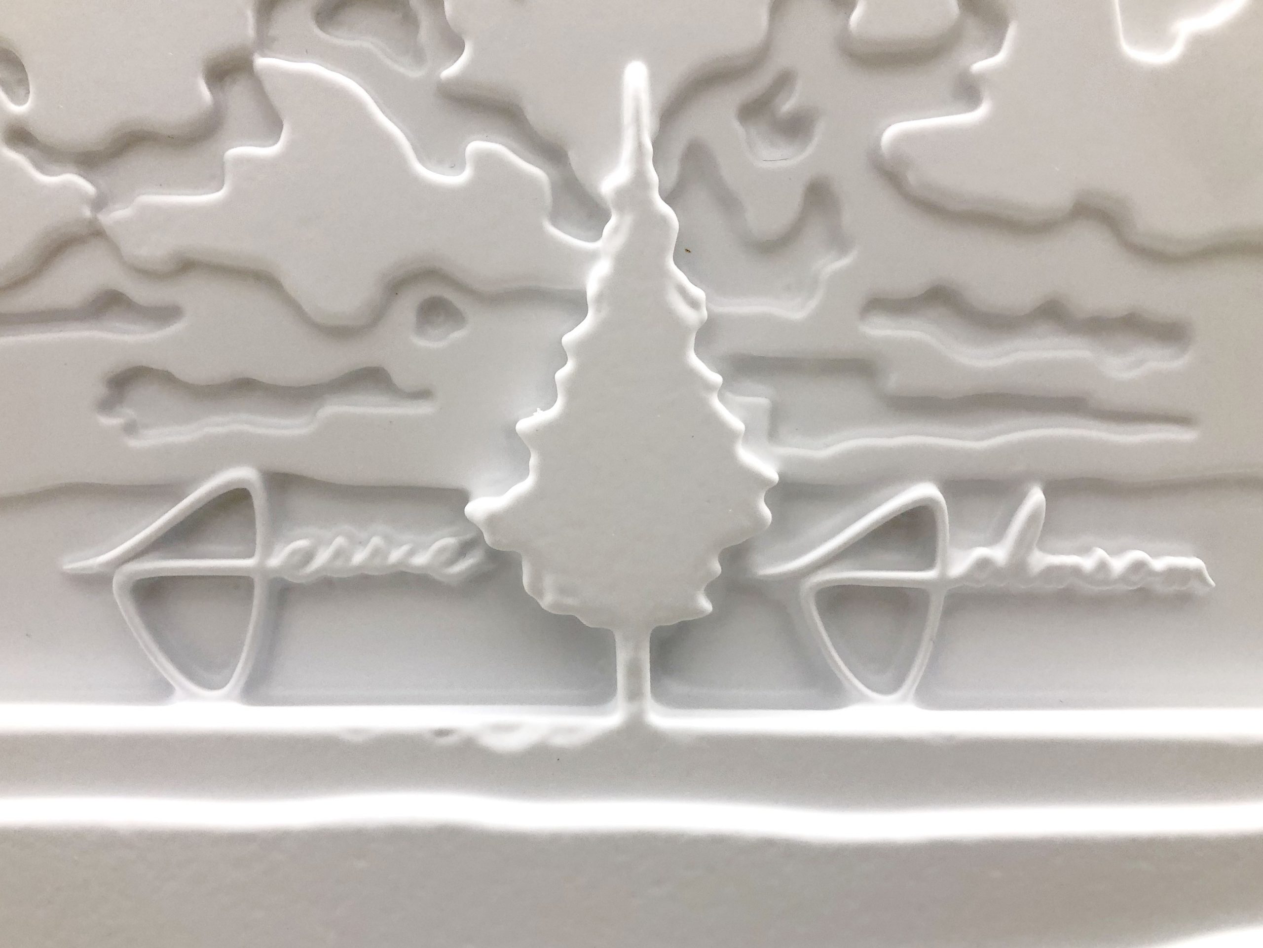
Although the Midwest was a large part of my upbringing, I grew up in North Carolina. Pine trees are prevalent in NC but do not grow in the part of the Midwest where my family comes from. Combining the pine tree with the Midwestern landscape tells the story of my journey and upbringing

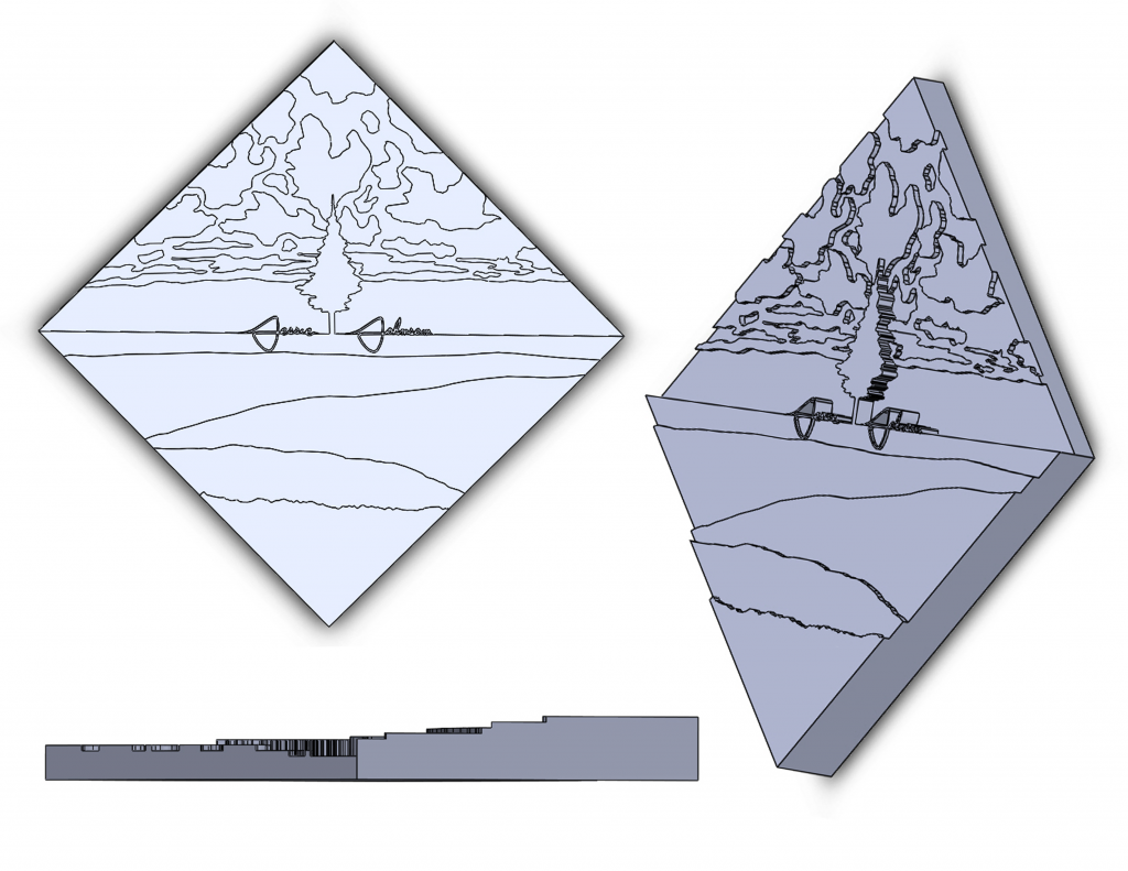
This picture is an initial composite I made in Photoshop to get a sense of the design I wanted to create.

I chose a diamond shape on which to display my landscape. The four corners of the diamond emphasize the expanses of the sky, horizon, and land. The diamond shape also draws special attention to the center where the pine tree is depicted.

Shown here are several variations of the design. 

My name was added to the sign in order for it be identifiable. I chose to use my signature as the cursive would follow the straight line of the horizon. 

egjszlk

Visualization & Planning

Detailed sketches were drawn to plan and visualize the building process. The first step would be to draft the mold in Solid works. Accounting for the future limitations of vacuum forming would be critical when modeling the design in Solid works. The model also needed to be able to adapt to the specifications of the CNC machine, which involved reducing the amount of small details throughout the design. Because of this, the signature would have to be laser cut separately from the mold, as the CNC machine would be unable to produce such fine details.

After being cut by the CNC machine and combined with the laser cut signature, there would still be a few more steps before being vacuum formed. Holes would have to be drilled throughout the piece so that the vacuum could reach tight spaces. Without the holes, many of the fine details in the design would be lost. 

Once vacuum formed, excess plastic would be carefully trimmed for a clean finish. Holes could be drilled into a lip in the plastic for mounting. 

After diagramming the process through sketches, it was time to create the mold in Solid works. Although it was intended for the CNC machine, having this three-dimensional model helped project what the final result would look like. It also revealed several issues I was unable to notice when sketching the design on paper. 

The signature was included in the model at first, but was later removed because of the limitations of the CNC machine. It was mostly used for comparing its size with other components in the design. 

Building Process

The Solid works model was sent to the CNC machine and the MDF mold was produced. Other than a few minor details, the result was nearly identical to the Solid works model and sketches made beforehand. 

IMG_3751
IMG_3759

A table saw was used to cut excess MDF off the mold. It was also used to create draft angles on the steep sides of the mold. With draft angles, the mold would be easier to remove from the vacuum formed plastic.

The mold after being trimmed by the table saw…

IMG_3756

The cursive signature was laser cut separately from the mold. Unfortunately, the horizon featured in the design turned out to be too small to hold the letters, so the signature was moved above into the sky.

Note the tight crevices and contrasting planar heights throughout the mold. The vacuum would have difficulty reaching these intricate spaces. As a result, the sign would lack indentations and look similar to a blanket lain on top of a few sharp corners. Holes were needed to prevent this from occurring. 

IMG_3758
IMG_3785

Holes were drilled liberally throughout the mold. Areas that were especially intricate, such as the signature area, were given more holes.

The holes were sanded so that they would not show when vacuum formed. 

IMG_3792

The long awaited moment: vacuum forming. As shown in the video, the process was a success. The details were revealed beautifully.

Unfortunately, the plastic had to be torn in order for the mold to be released. Some tears were a bit large, as shown here. The draft angles on the mold were probably too steep for it to release easily. 

A bit of glue to mend the tears had a surprisingly seamless result. The glue was applied on the inside of the plastic so that the outside would remain clean.

Lastly, the plastic was trimmed for a clean finish. Unlike in the original plans, the sign was trimmed to have a vertical face rather than having a lip. It did not need a lip with a drilled hole because the corner of the sign could successfully hang on a push pin.

Final

Final Notes

This project taught me a lot about the importance of planning and forethought in the design process. Every step and its associated limitations had to be accounted for. I was also introduced to many new techniques such as using CAD, the CNC machine, and the vacuum former. Overall, my abilities have grown through this process and I can now approach problems with a new mindset.